Adding a date coder to a working production line is more than mounting a printer beside the belt. The equipment must mark each product clearly, at the right time, without disrupting established flow. This guide explores how to integrate a date coder into an existing conveyor, from assessing the line to checking the first printed samples. Small details matter. Product spacing, belt speed, package shape, and available mounting space can all affect the result.
Before choosing a setup, measure the conveyor and observe products as they move. Note where a sensor can detect each item, how much clearance the printhead needs, and whether packages shift or rotate. A bracket that looks secure while the belt is stopped may vibrate during operation. That deserves a real test. The guide also covers basic coordination between the coder, sensor, conveyor controls, and any existing inspection equipment. A qualified technician can help confirm compatibility and follow the equipment manufacturer’s installation instructions.
After installation, test the system at normal operating speed using representative products. Inspect print position, legibility, and consistency across multiple packages, then adjust settings as needed. One assumption often deserves another look: a sample printed successfully by hand may not represent a fast-moving line. Production conditions can expose missed triggers or uneven spacing. Careful observation helps identify those issues before routine operation begins. No setup is perfect on the first attempt, and documenting adjustments makes later troubleshooting easier.
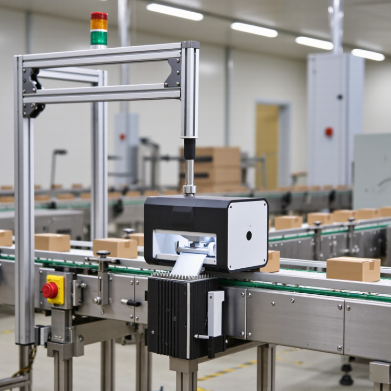
Integrating a date coder into an existing conveyor starts with measurements, not a model number. Record belt speed in meters per minute while the line runs at its normal production rate. Check more than one setting if operators change speeds during a shift. A handheld tachometer or timed measurement of belt travel can verify the drive display. Small errors matter.
Then measure product pitch: the distance from one package’s leading edge to the next. Observe production for a full minute, noting gaps, overlap, and uneven spacing. For example, a line moving at 24 m/min with 120 mm pitch carries about 200 packages per minute. This estimate helps determine the required print frequency and available time for each mark. Confirm it with actual counts; cartons rarely stay perfectly spaced.
Speed and pitch also help identify a workable coder position. At 24 m/min, the belt travels about 400 mm each second, so the trigger window can be brief. Match the sensor, printhead position, and mounting clearance to the real product path. Allow for acceleration, belt slip, and package wobble. A display reading may look exact, but it can be wrong. Recheck measurements after installation, then inspect test marks at normal speed. A careful estimate is useful, not final.
At 30 metres per minute and 250-millimetre package gaps, the line needs about 120 prints per minute. Allow headroom. Acceleration, uneven spacing, and brief stops can increase demand.
GS1 specifies a minimum X-dimension of 0.264 mm. At 300 dpi, each dot is about 0.085 mm wide, leaving roughly three dots across the narrow bar. That margin is thin. Film movement or ink spread may soften the edges.
Test codes at normal production speed on the actual packaging material. Use a verifier to check the required grade on ISO/IEC 15416’s 0.0-to-4.0 scale. Test it live. A sharp sample on a stationary carton is not enough.
Measure from the printhead face to the package surface, not the conveyor rail. Follow the equipment manufacturer’s specified range; there is no universal gap. Check several belt positions, then recheck after adjustments.
Check standoff, head alignment, and package movement before changing print settings. Compare samples across different surfaces and at the fastest planned speed. I would not trust one clean carton as proof of a stable line.
The encoder tracks conveyor travel, while the photoeye detects each product’s leading edge and starts the print cycle. Mount the encoder where it keeps steady contact. Slippage can shift print position during acceleration.
No. Its output type, wiring polarity, and input common must match the coder or controller. Follow wiring diagrams and isolate power before connecting. Test packages with different gaps and speeds; small timing errors show up quickly.
Learning how to integrate a date coder into an existing conveyor starts with understanding the line. Measure conveyor speed in meters per minute and the distance between products before choosing equipment. Then confirm that the coder’s throughput and print resolution can meet production demands while keeping codes clear and readable.
During installation, position the printhead within the manufacturer’s specified standoff range, measured in millimeters. Use an encoder to track conveyor movement and coordinate print timing, and check that the photoeye inputs and outputs are compatible with the system’s 24 VDC requirements. Finally, verify that the coder’s enclosure protection suits the operating environment by checking its IEC 60529 IP rating. These steps help ensure reliable, well-timed printing without disrupting normal conveyor operation.

 Collins Machine